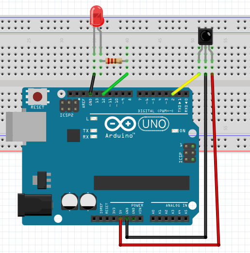
Solved You are using a photodiode to measure a signal with a Circuit Diagram
Solved You are using a photodiode to measure a signal with a Circuit Diagram This circuit is designed to measure light intensity using a photodiode and a resistor to create a voltage divider, with the signal read by the Arduino Nano's A0 pin. A yellow LED is connected to the D2 pin, potentially serving as an indicator. The 9V battery powers the circuit, and the Arduino's code is yet to be implemented for specific
I'm using a RPI 3B and I'm reading photodiode outputs by passing them through an ADC (MCP3008). I used the setup and code in the link below as a reference. Except I've replaced the LDR with a photodiode, with the cathode of the photodiode connected to the resistor. I am also using an 8k ohm resistor instead.
Measuring light intensity using photodiode BPW21R Circuit Diagram
Circuit for light intensity measurement Circuit for light intensity measurement. The circuit uses a p-n photodiode as the light sensor and a display driver IC LM3915 (IC1) to give a logarithmic current scale linearly with the incident light energy. The photodiode has a high-frequency response and fast switching speed of one nanosecond compared
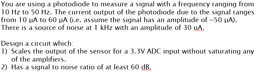
I'm trying to use a photodiode to measure light levels via an ADC on an ATMega168. I've got the microcontroller code working properly (measuring values on a pin and reporting it as an led brightness) but I'm having trouble getting the photodiode to report a voltage dependent on light levels. // Define the analog input pin connected to the photodiode and the op-amp output const int photodiodePin = 12 ; const int amplifierPin =10; // Define the LED pin if necessary const int ledPin = 4; void setup() { // Initialize the LED pin as an output if used pinMode(ledPin, OUTPUT); // Initialize the analog input pin pinMode(photodiodePin, INPUT); pinMode(amplifierPin, INPUT); // Initialize Hi, I want to use a BPW20RF photodiode and an operational amplifier. I am very new to all this and got confused how to set up the amplifier. When I directly plug in the photodiode in A0 and use a reference resistor of 30 Ohm, I get values of 0 to ~80 if I point directly with a flashlight on the sensor. Using an op-amp I want to increase this voltage to cover the whole level of 0 to 1023. Im
Photodiode Light Detector With Arduino Guide Circuit Diagram
I am running a photodiode through an op-amp circuit (trans-impedance amplifier.) I have been told I should characterize this device. I'm assuming he means using the voltage I get at a given distance and link this with the intensity of light by use of an equation. I moved the sensor back 5mm at a time taking readings etc., etc.