design an asynchronous pacemaker timing circuit using a 555 timer chip Circuit Diagram
design an asynchronous pacemaker timing circuit using a 555 timer chip Circuit Diagram For comparison, in figs 10 and 11 I set up another 555 timer on my breadboard, identically to the setup of the first 555, but I used a 0.47uF capacitor instead of a 1uF. I calculated the duration of the pulse for this new circuit: t = 1.1*R*C seconds t = 1.1*5100*0.00000047 t = 2.64 ms, approximately half of the duration of the first 555 timer
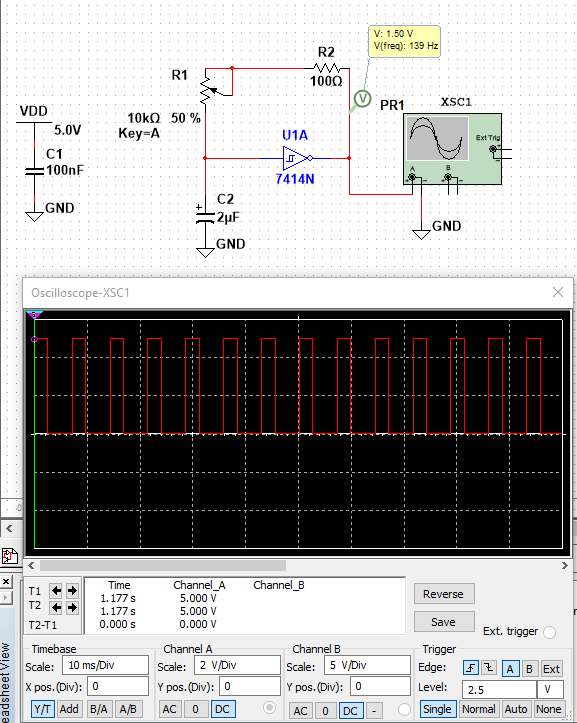
In this video you will learn how to make a pulse/wave generator with varying frequency with help NE555 timer IC.For more information and circuit check the ar This is a pulse generator with adjustable duty cycle made with the 555 timer IC. The circuit is an astable multivibrator with a 50% pulse duty cycle. The difference from the standard design of a 555 timer is the resistance between pins 6 and 7 of the IC composed of P1, P2, R2, D1 and D2. The diodes D1 and D2 set a definite charging time for C1
Pulse Generator : 9 Steps (with Pictures) Circuit Diagram
Hello! For my very first instructable I wanted to show how to build a pulse generator circuit using the ever so popular 555 timer chip. This is a very simple, yet very important, circuit to build and understand. It provides a great introduction into integrated circuits and the 555 chip finds its way into many more sophisticated circuits.
Welcome to my channel! In this video, I'll show you how to create a simple and effective clock circuit or pulse generator using the versatile 555 timer IC. W

How To Make Pulse Generator Using Circuit Diagram
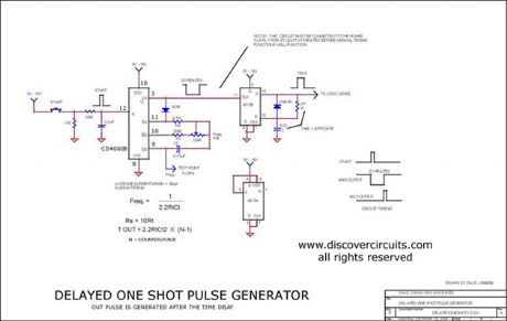
How the Circuit Works. Any one of the total four gates can be used to produce an oscillator with a variable duty-cycle and a set frequency. The RC time-constant of this network that has a capacitor C1 and resistor R1+P1 helps in determining the pulse duration. This is sometimes called a one-shot circuit. The time it stays HIGH is decided by the size of a resistor and a capacitor. The higher the values, the longer it stays HIGH. If you connect a buzzer to the output, you can create an alarm circuit that is triggered for example by a window being opened. 555 Timer One-Shot Example Circuit
